|
|

|
|
|
| Construction of the
Berkeley Ground Station |
|
|
| |
| Project Description |
| |
|
The Berkeley Ground Station consists of a parabolic dish antenna with its associated
electronics and data processing equipment. The antenna, 11 meters (36 feet) in diameter, will be installed in the
Berkeley hills close to Space Sciences Laboratory.
The Ground Breaking Ceremony for the Berkeley
Ground Station was held on September 23, 1998. Development of the antenna site will take place in two phases. Phase
I comprises casting of the the concrete foundation and started on October 22, 1998, and was completed on November
17, 1998. Tree removal occurred on April 23 and 25, 1999.
Phase II work started on May 10, 1999 and comprises leveling of the area
around the antenna site, paving of an area around the antenna base, reinforcement of the access road, and installation
of utilities, drainage, fencing and lighting. Installation of the antenna at SSL occurred in October 1999.
|
| |
| |
| |
| Site Development |
| |
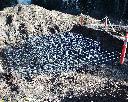 |
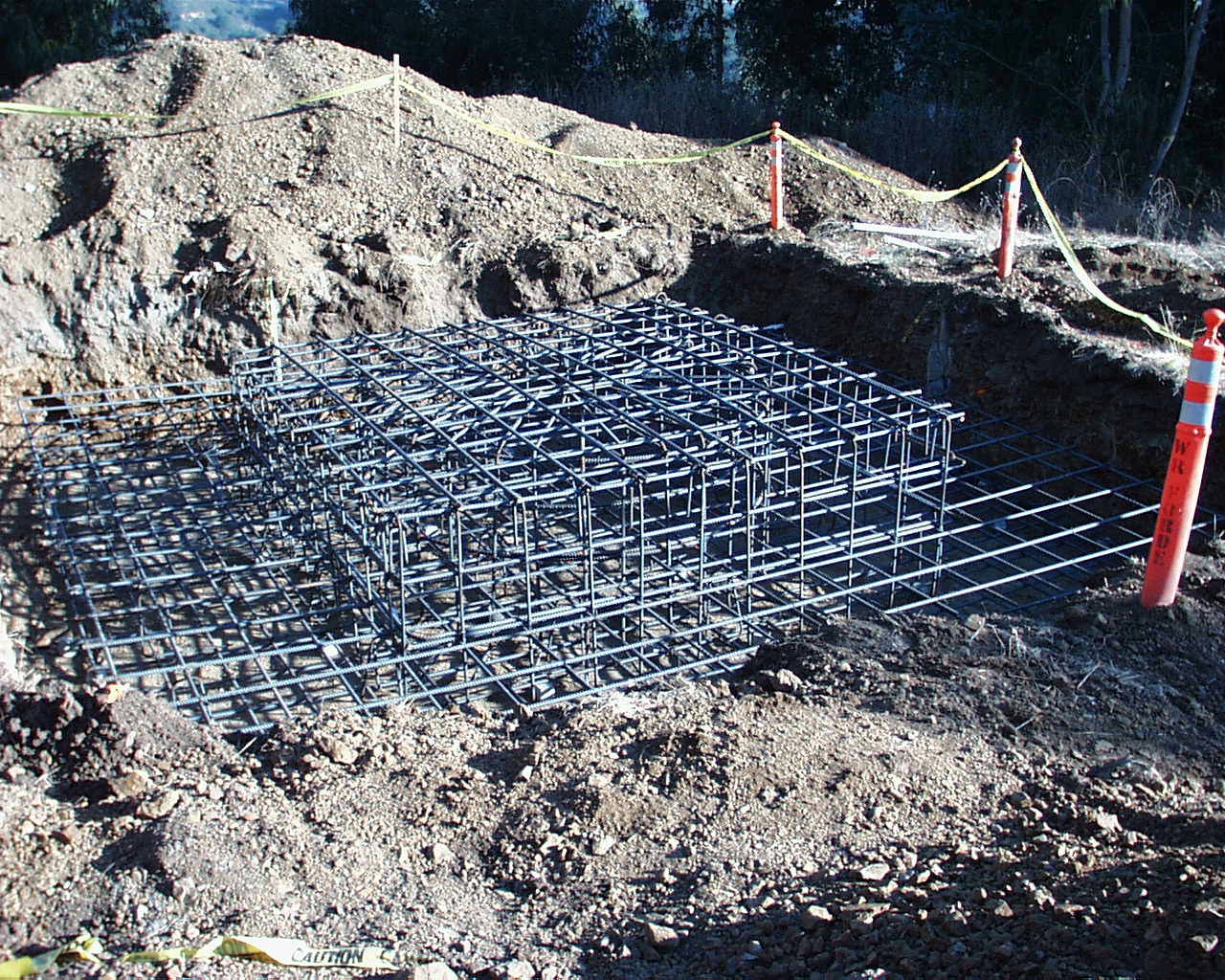
Rebar matting for the antenna foundation (October 26, 1998). View from north. |
 |
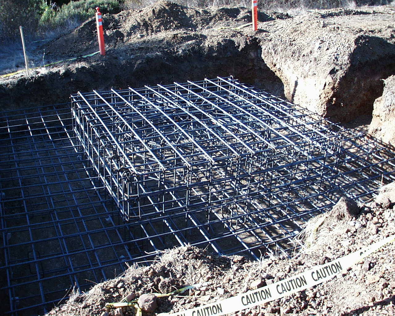
Rebar matting for the antenna foundation (October 26, 1998). View from south. |
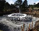 |
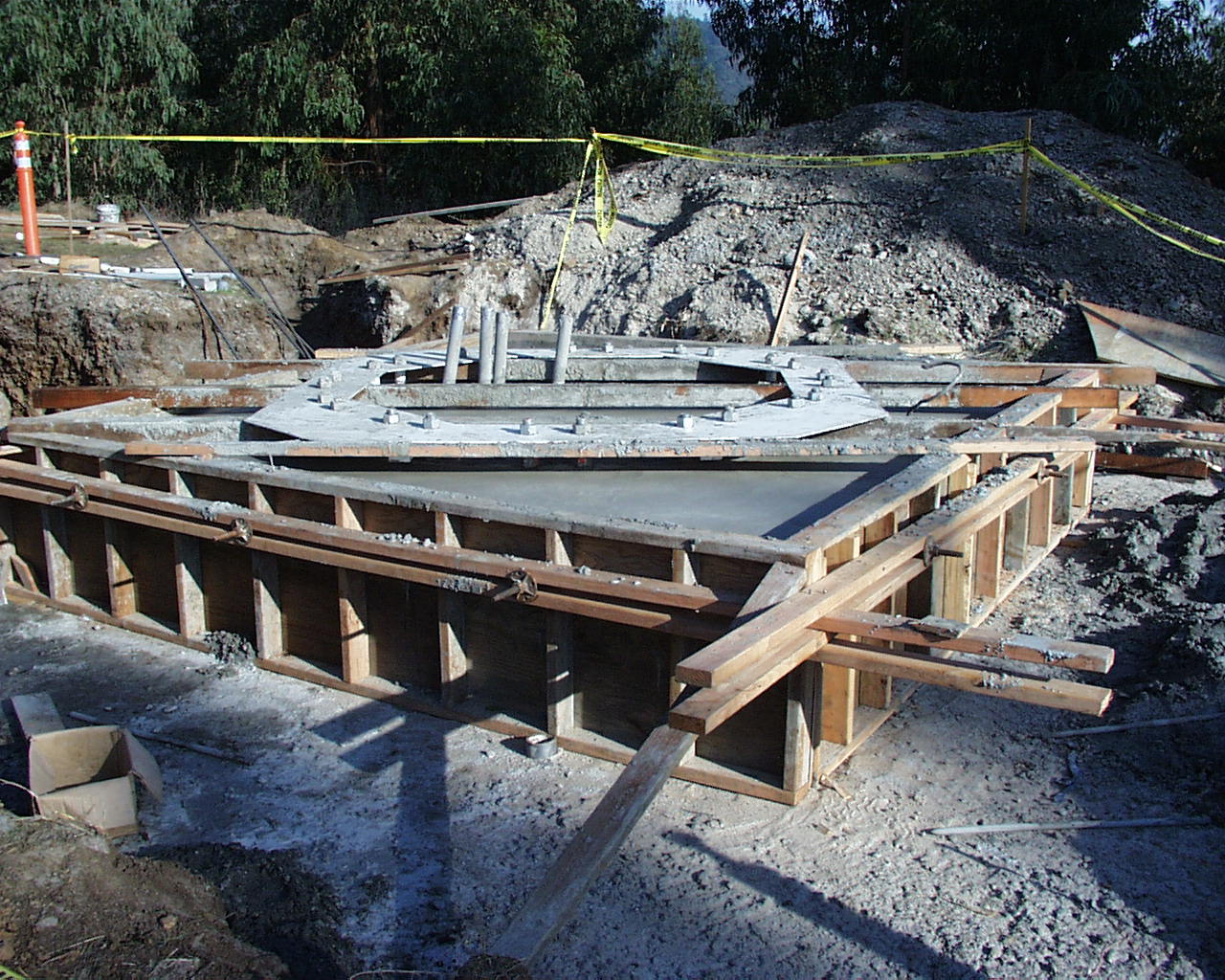
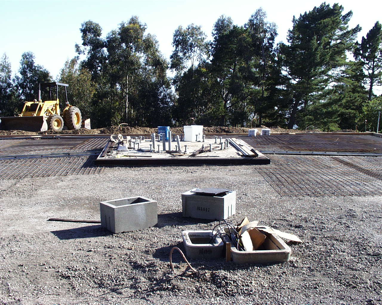
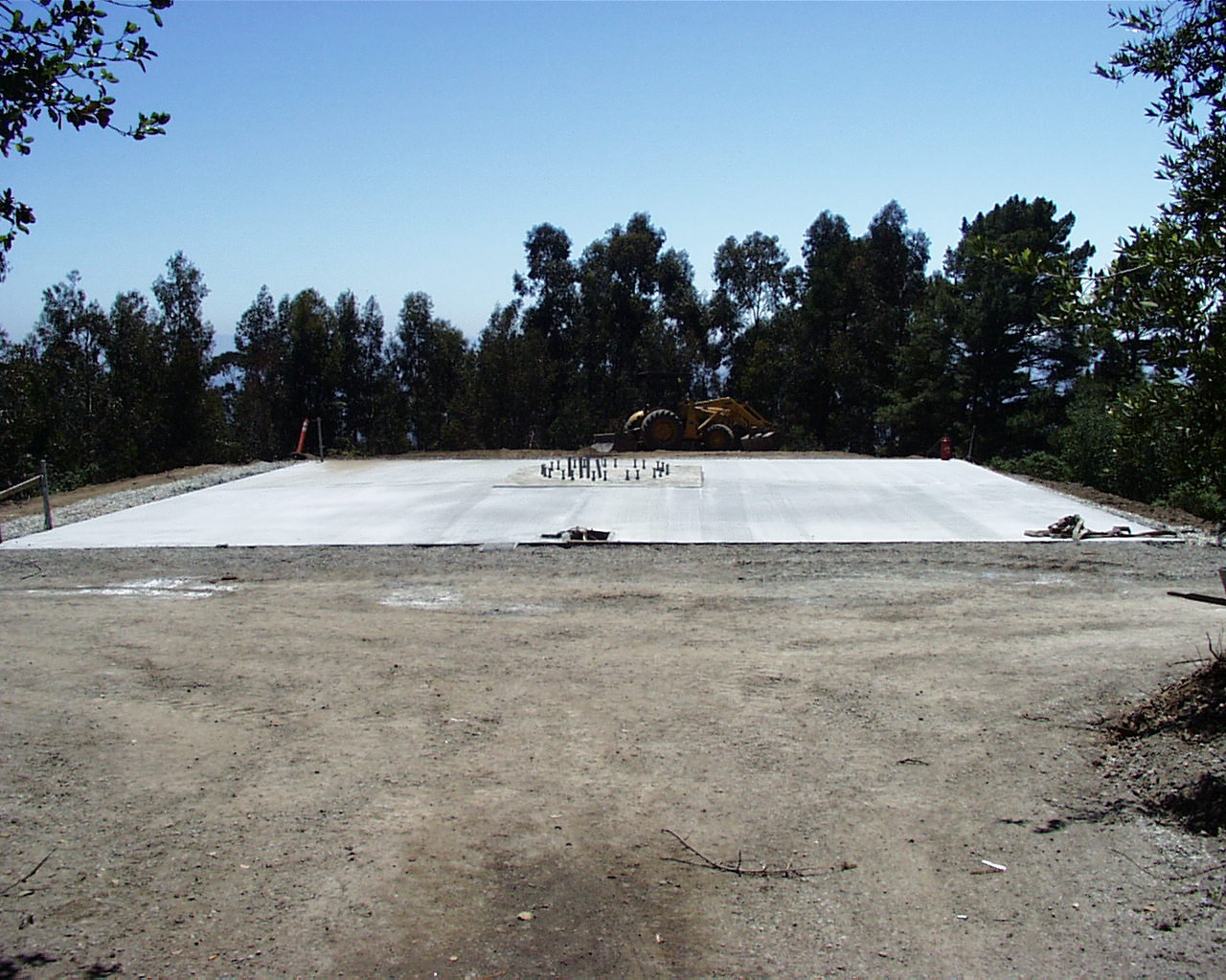
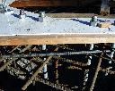
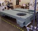
The first 159,000 pounds (39.25 cubic yards) have been poured (November 5, 1998).
The white template will be used to correctly place the 24 bolts that will tie down the antenna pedestal. View from
east. |
 |
Partly finished foundation (November 5, 1998). View from west. |
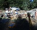 |
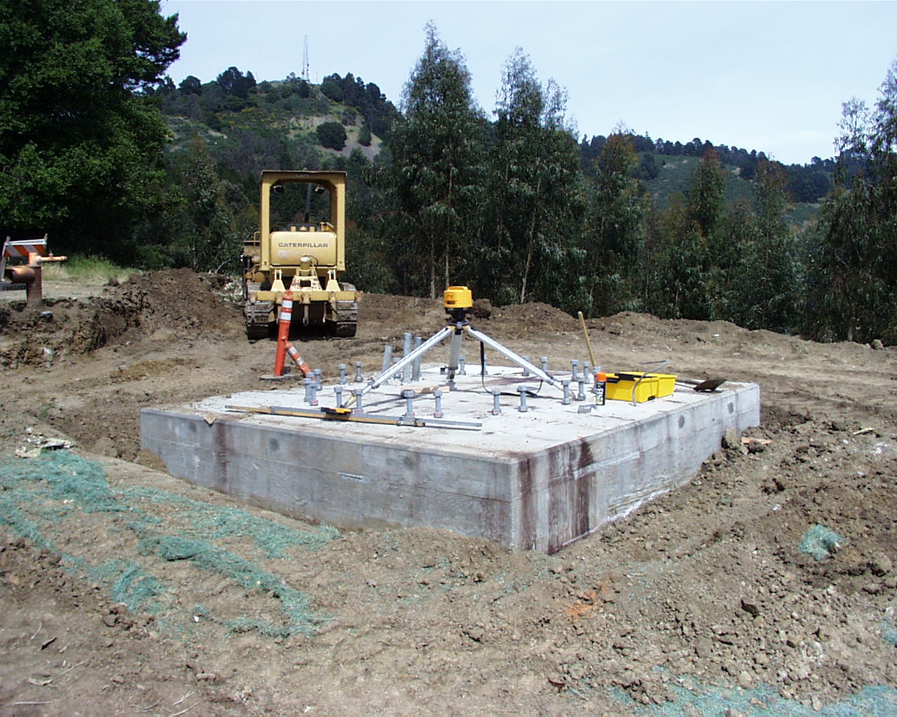
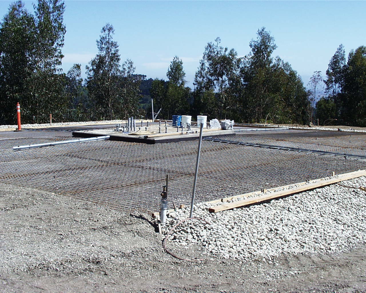
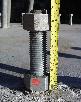
Construction crew preparing the foundation for the second concrete pour (November
12, 1998). Note the laser leveling system in the foreground to the right. This system is used to align the template
and the tops of all 24 tie-down bolts. View from south-west. |
 |
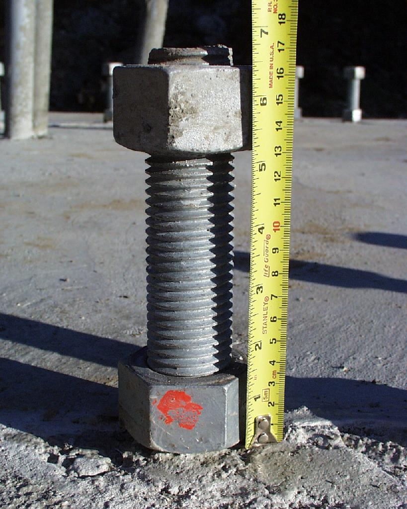
Detail of the foundation before the second concrete pour (November 12, 1998). The
24 tie-down bolts are 1.5 inches in diameter and 28 inches long. View from west. |
 |
Foundation after the second concrete pour of 10.5 cubic yards (November 13, 1998).
Total weight of the finished foundation is 201,500 pds (about 92 tons). View from west. |
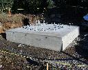 |
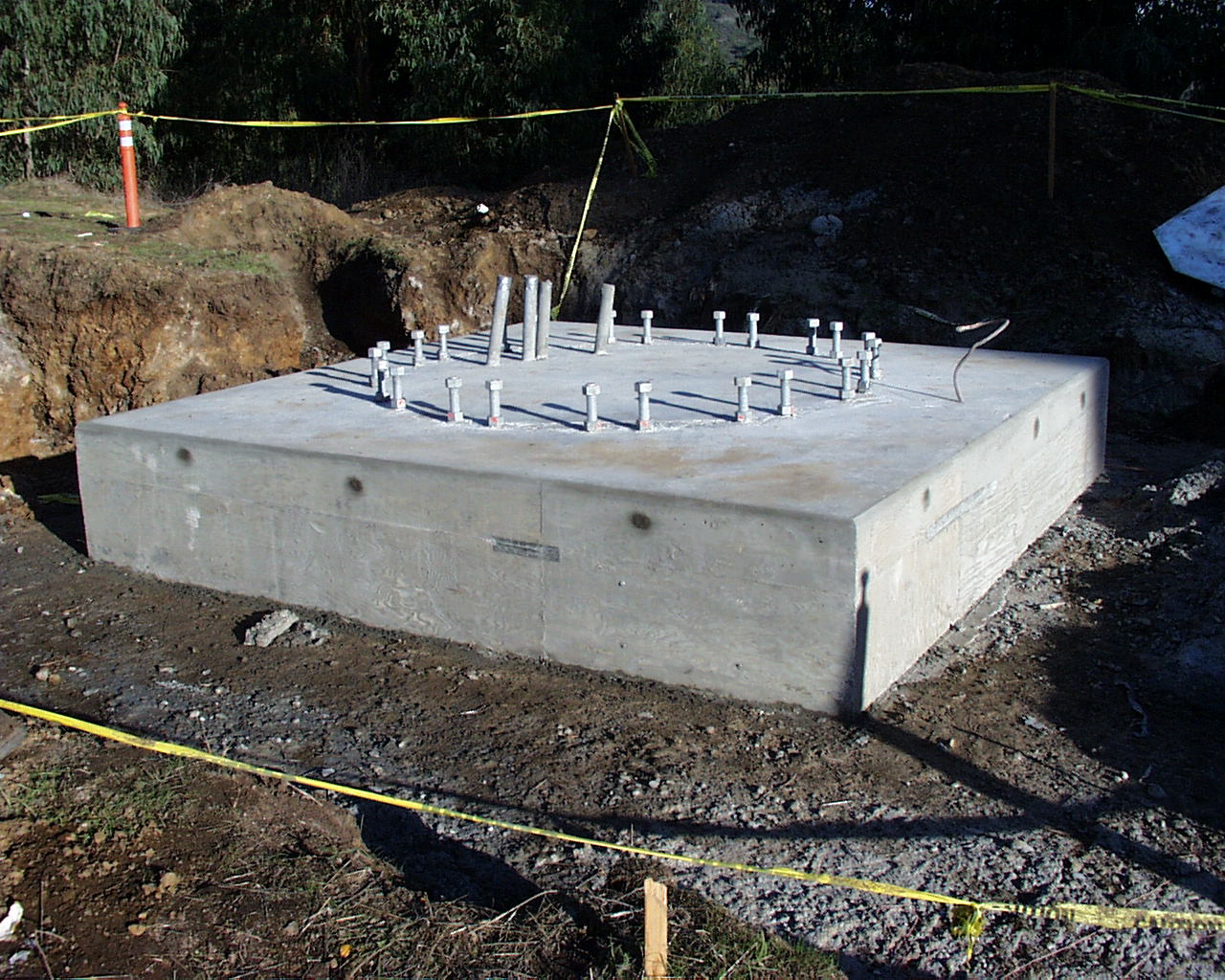
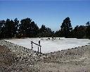
Finished antenna foundation (November 17, 1998). View from north-west. |
 |
Each one of the 24 bolts is perfectly aligned (November 17, 1998). View from north-west. |
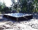 |
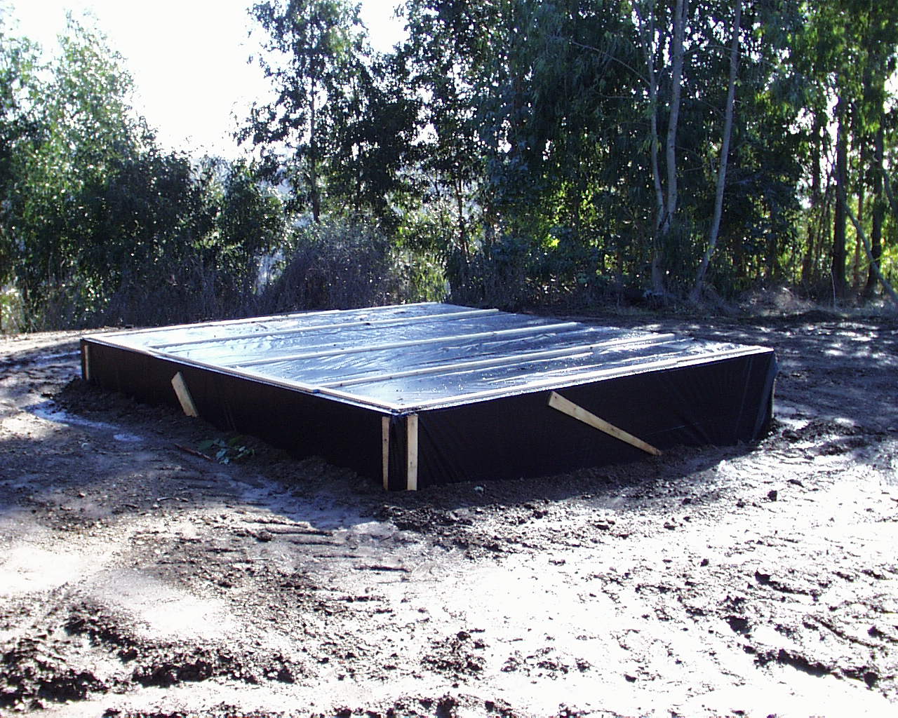
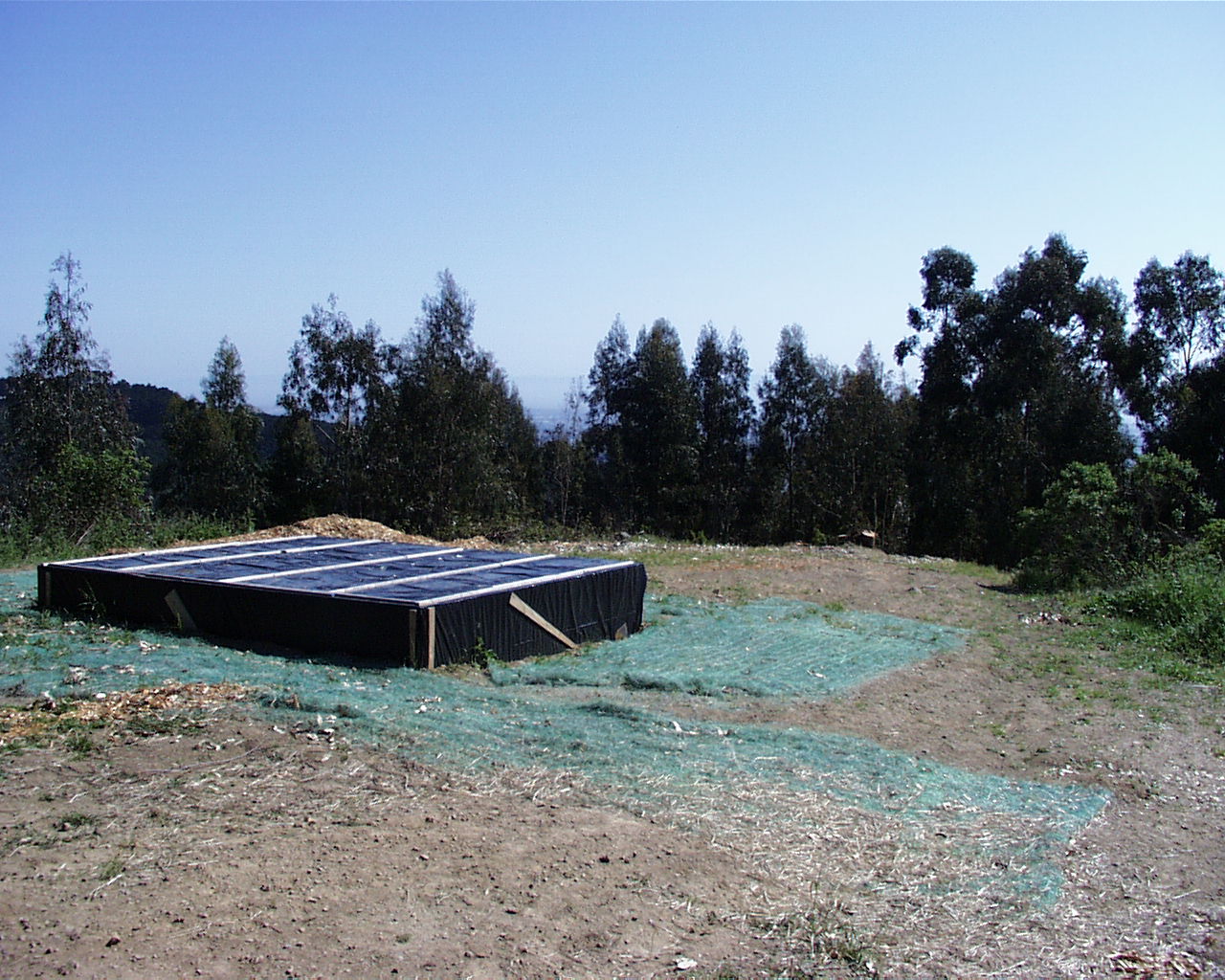
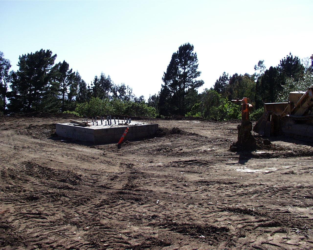
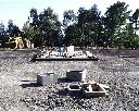
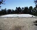
Phase I of the site construction is complete. The soil has been filled in and the
top of the foundation is protected for the winter, until Phase II will commence (November 25, 1998). View from
north-west. |
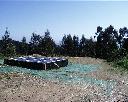 |
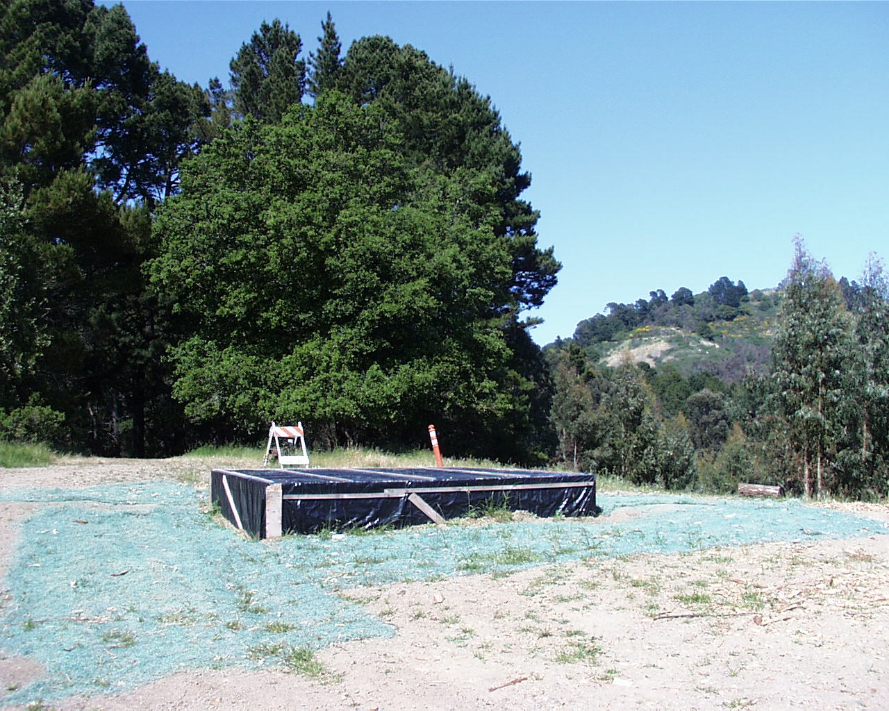
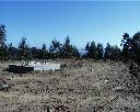
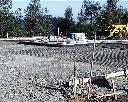
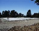
Site view from north after eucalyptus tree removal (May 7, 1999). Proposed crane
location is in the immediate foreground. |
 |
Site view from west after tree removal (May 7, 1999). Oak and fir trees were not
removed. Proposed dish assembly area is in the immediate foreground. |
 |
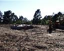
Phase II site work has started by leveling of the area around the antenna base (May
10, 1999). |
 |
Leveled site, view from north (May 11, 1999). |
 |
Leveled site, view from east (May 11, 1999). |
 |
View from the entrance to the site (May 11, 1999). |
 |
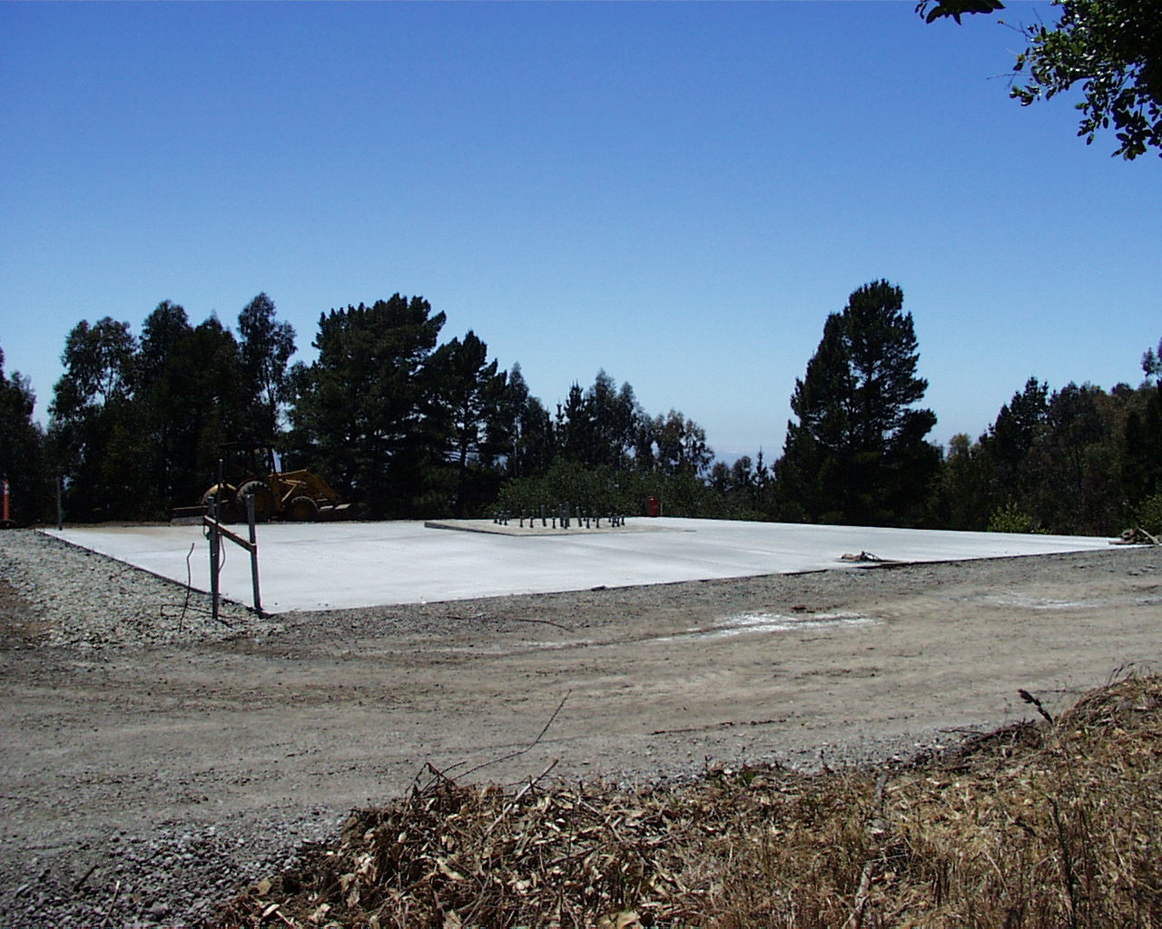
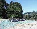
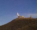
View of the antenna site from north (June 11, 1999). |
 |
View of the antenna site from north (June 11, 1999). |
 |
View from north-east. Pull boxes for power and communications lines are visible in
the foreground (June 11, 1999). |
 |
View from south (June 11, 1999). |
 |
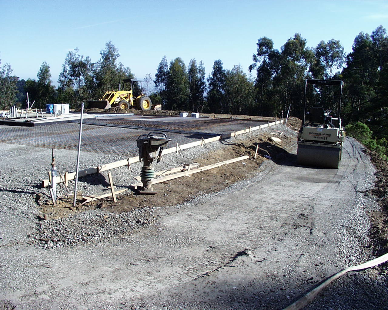
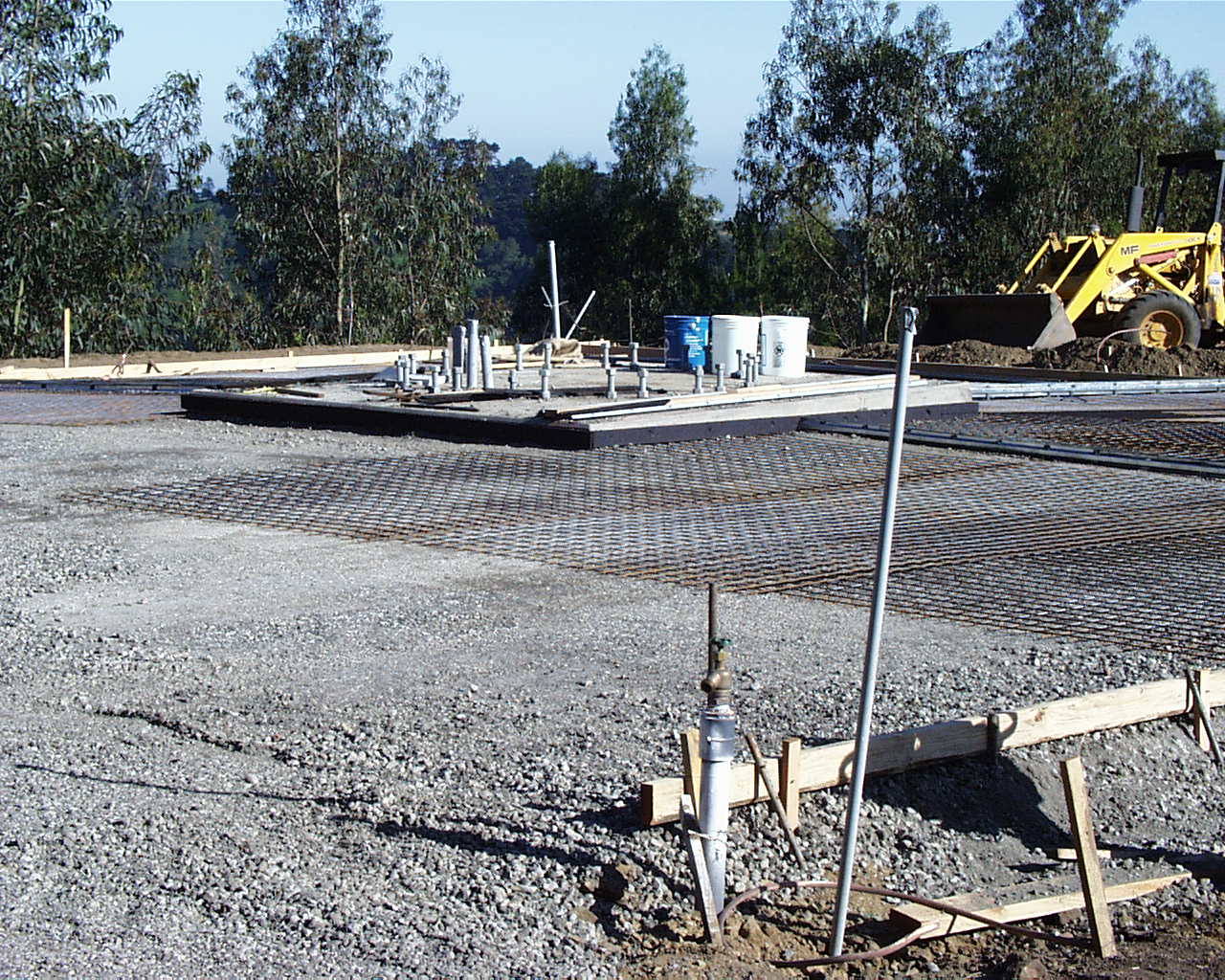
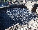
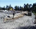
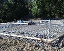
View of the antenna site from north. Rebar matting has been laid in preparation of
the final concrete pour (June 15, 1999). |
 |
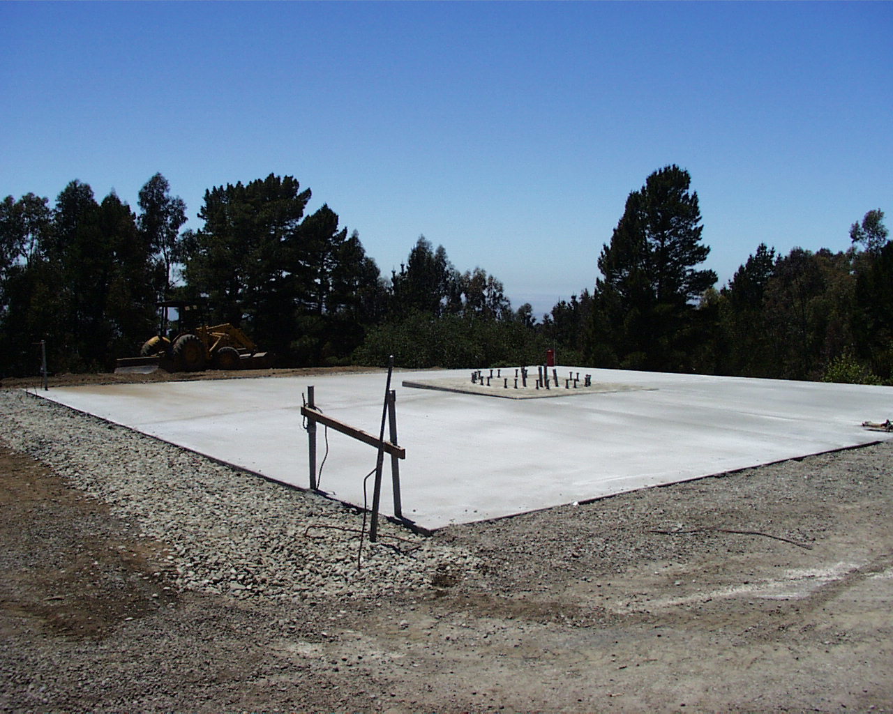
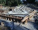
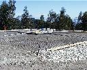
View of the almost finished antenna site from east. An additional 27 cubic yards
of concrete have been poured to form a clean working area around the antenna base (June 15, 1999). |
 |
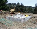
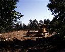
View from east. The crane needed for the antenna installation can be positioned in
the immediate foreground. The dish can be assembled in the area where the tractor is parked (June 15, 1999). |
 |
View from the driveway (north-east) toward the antenna site (June 15, 1999). |
 |
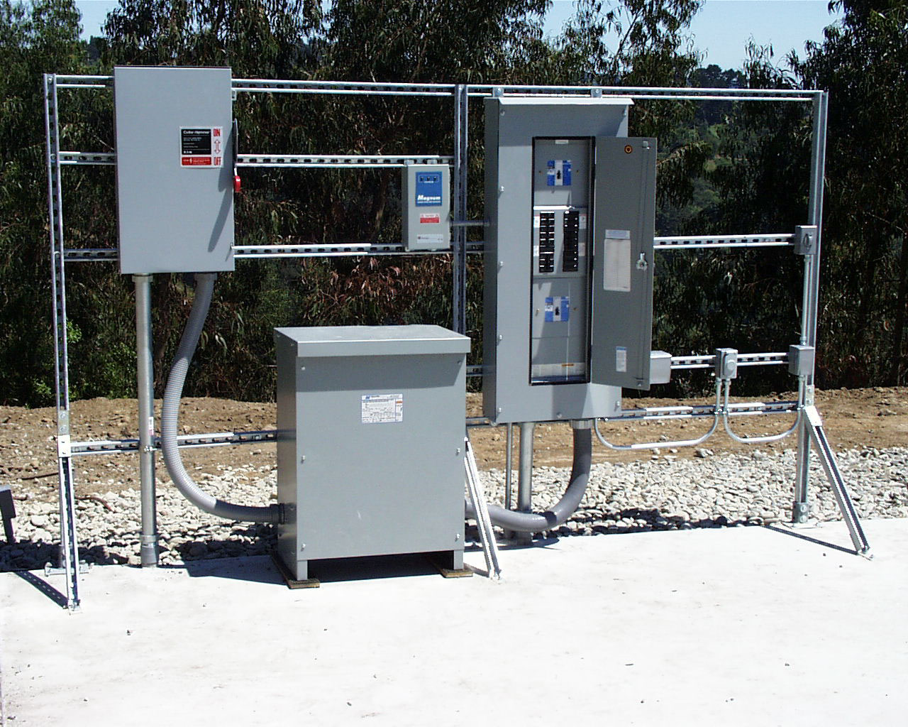
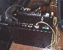
Circuit breaker panel and transformer (July 10, 1999). |
|
|
Antenna Construction
 |
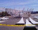
Support structure and 12 of 24 reflector segments installed (February 1999). |
 |
Support structure and 12 of 24 reflector segments installed (February 1999). |
|
 |
The painted reflector has been shipped to EMP Systems in Southern California for integration
with the complete ground station (March 1999). |
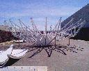 |
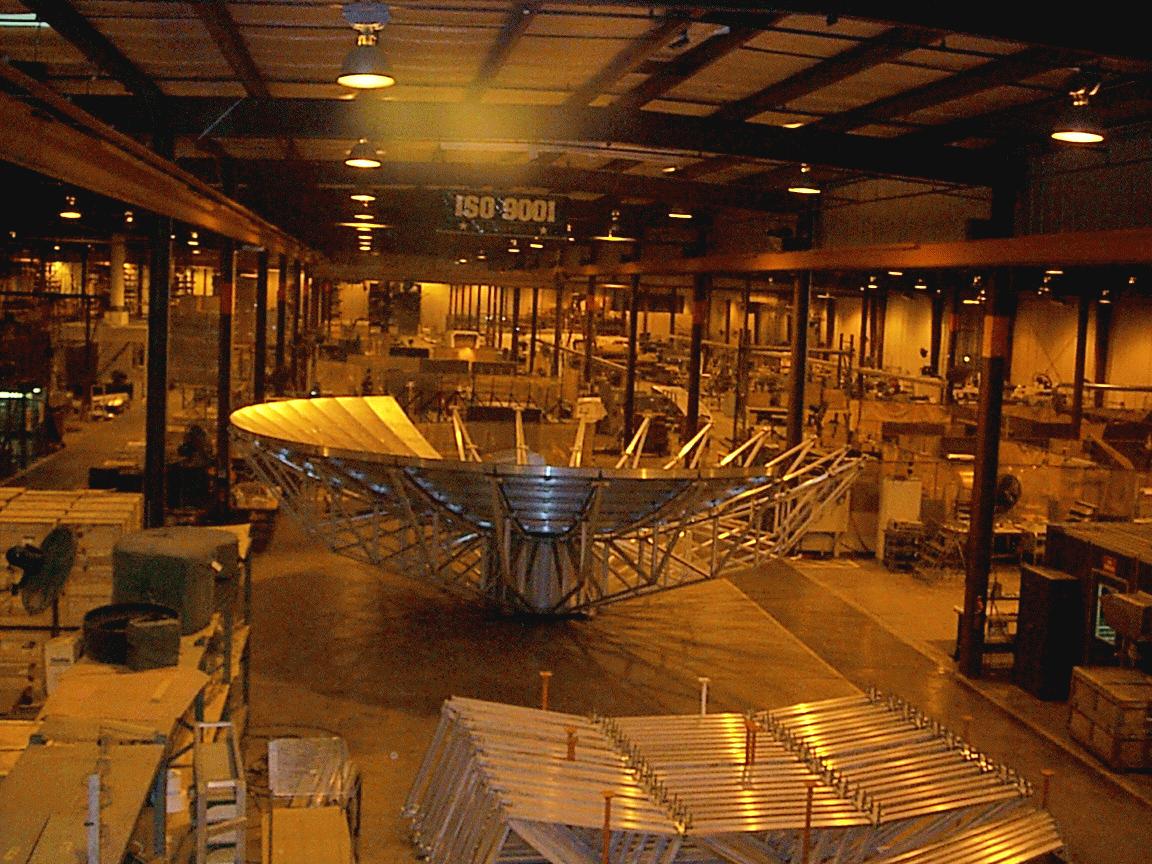
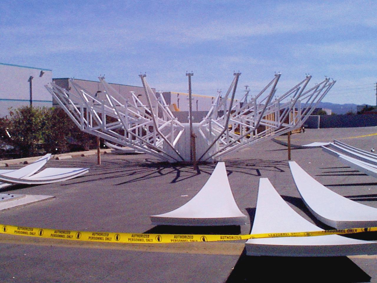
View of the assembled support structure and some of the reflector segments (March
1999). |
|
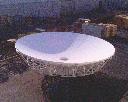 |
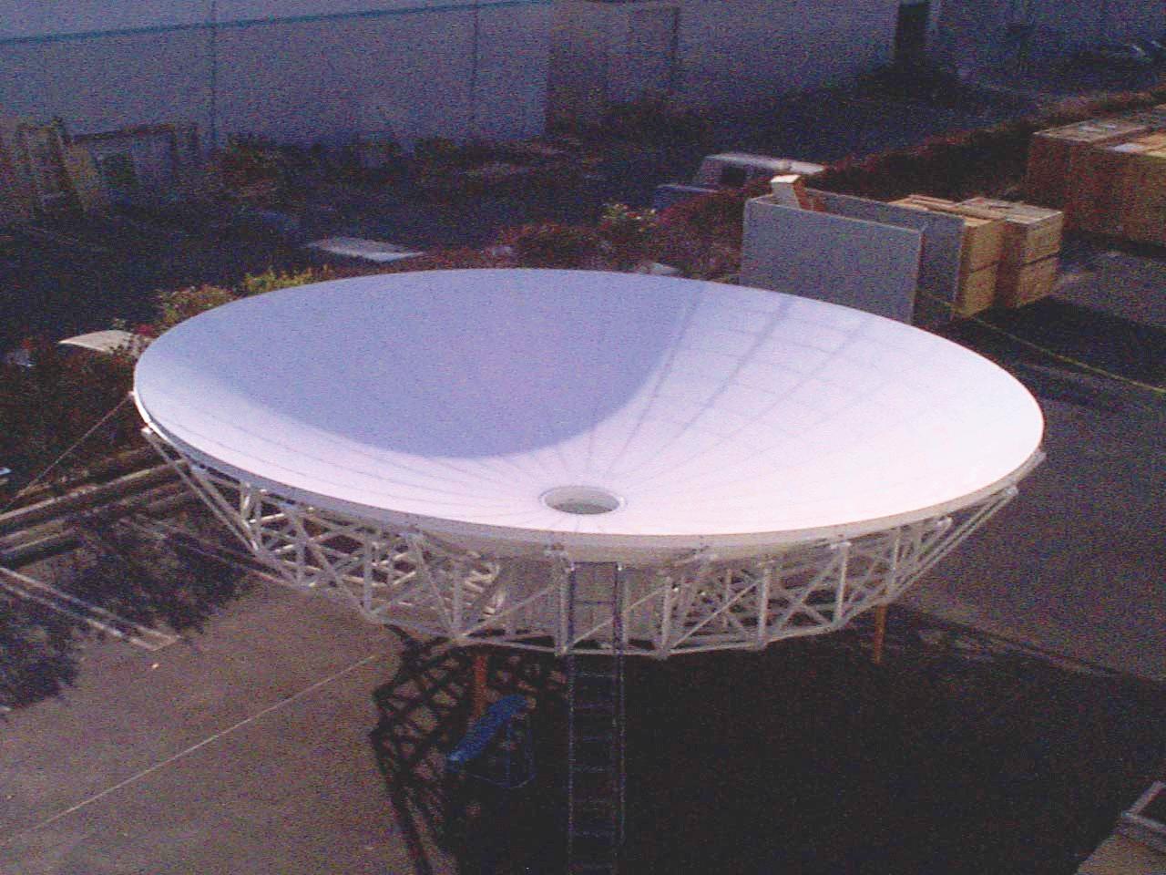
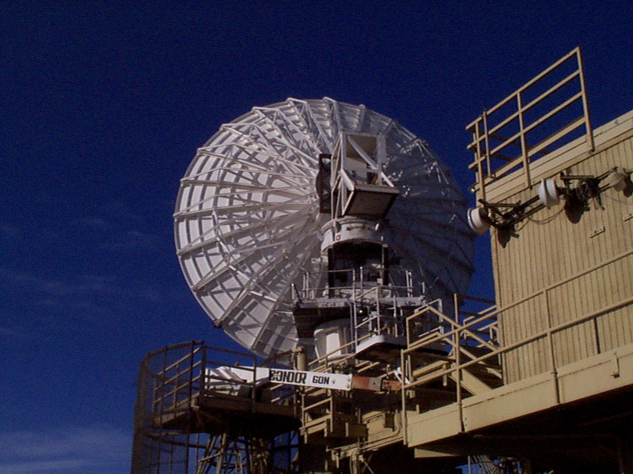
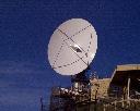
View of the completely assembled 11 meter reflector. The reflector weighs approximately
6,800 pounds (March 1999). |
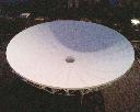 |
View of the completely assembled 11 meter reflector (March 1999). |
|
 |
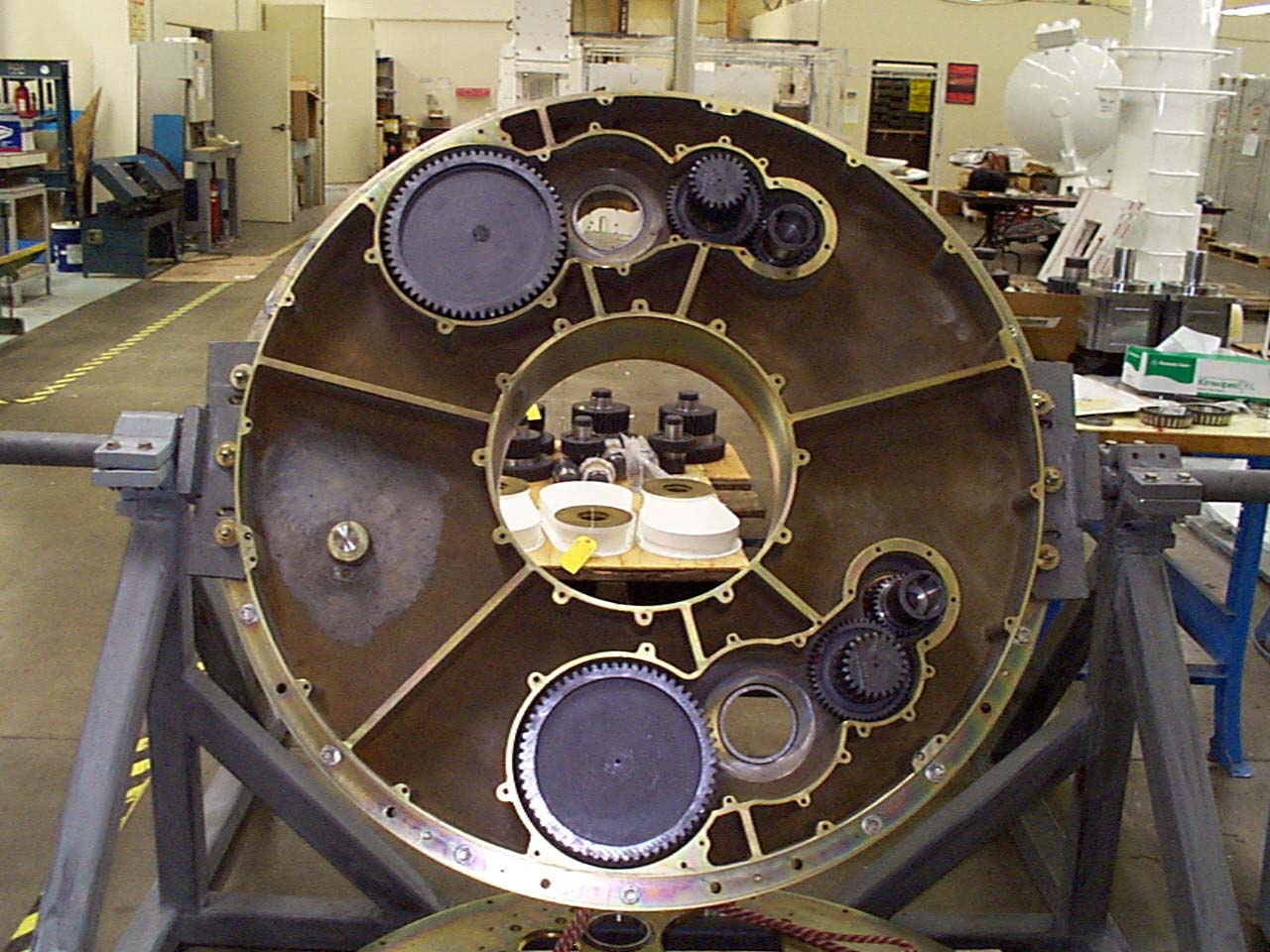
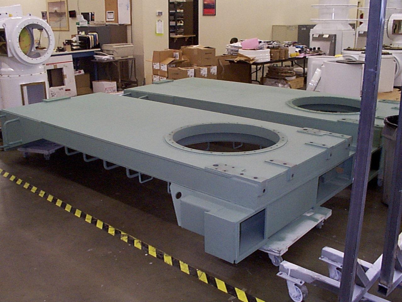
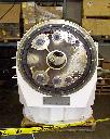
Riser base, azimuth/elevation gear box, yoke arms and cross-elevation arms at EMP Systems
(May 3, 1999). |
 |
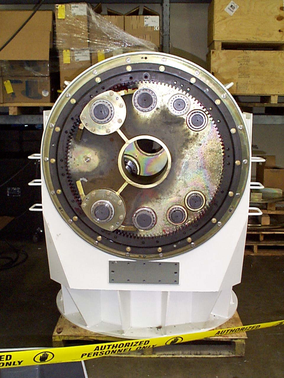
Azimuth/elevation gear assembly (May 3, 1999). |
|
 |
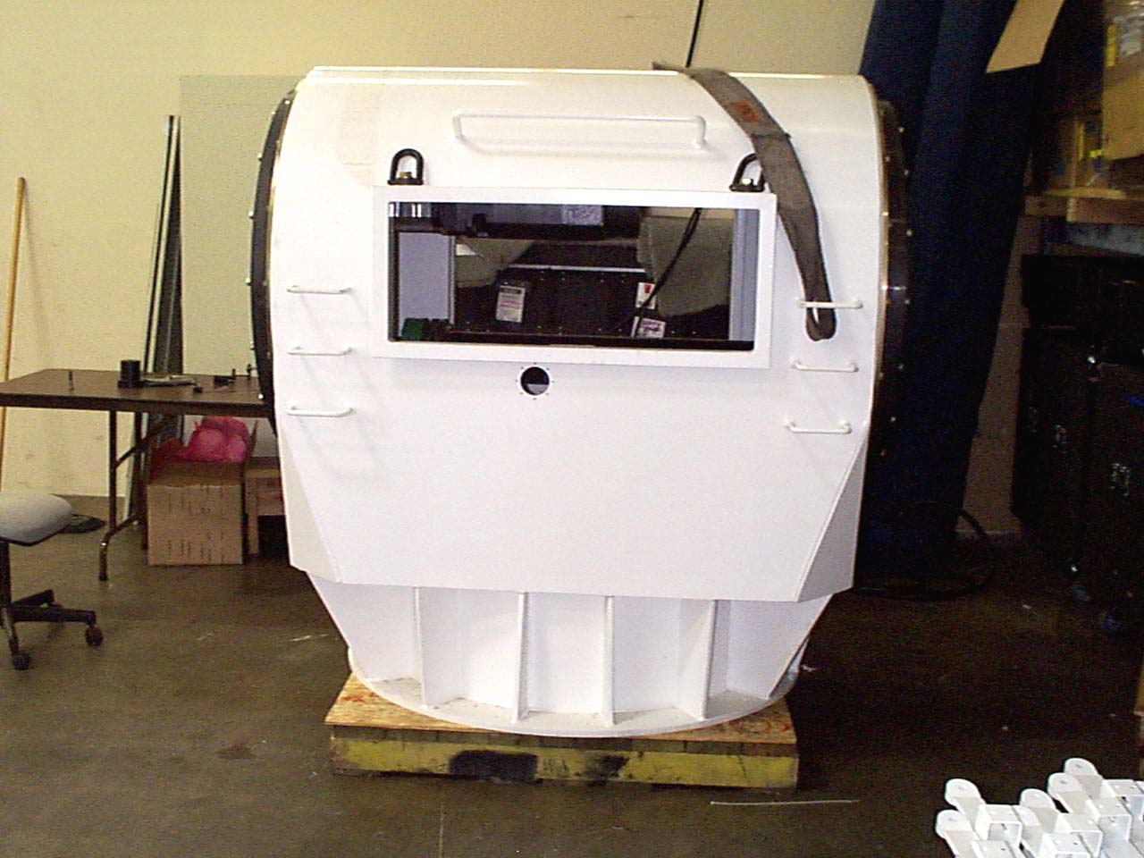
Assembled riser base for the 11 meter antenna (May 3, 1999). |
 |
View of the elevation gear box (May 3, 1999). |
|
 |
View of the azimuth gear box at EMP Systems (May 3, 1999). |
 |
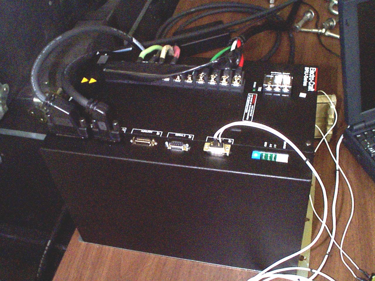
Elevation servo amplifier on test stand (May 3, 1999). |
|
 |
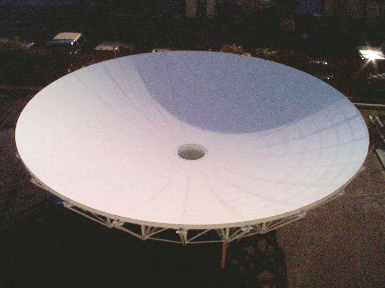
Reflector on test stand, overlooking the San Fernando Valley (May 17, 1999). |
 |
Reflector on test stand - front view with X-band feed system. This feed system has
been tested for the twin of the Berkeley antenna (May 17, 1999). |
|
 |
Reflector on test stand - rear view (May 17, 1999). |
 |
Assembled gear boxes and yoke arms at EMP Systems (May 17, 1999). |
|
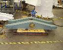 |
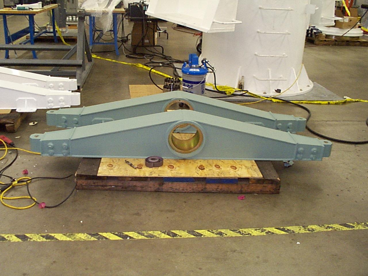
Cross-elevation arms at EMP
Systems (June 10, 1999). |
 |
Yoke arms painted green (June 10, 1999). |
|
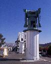 |
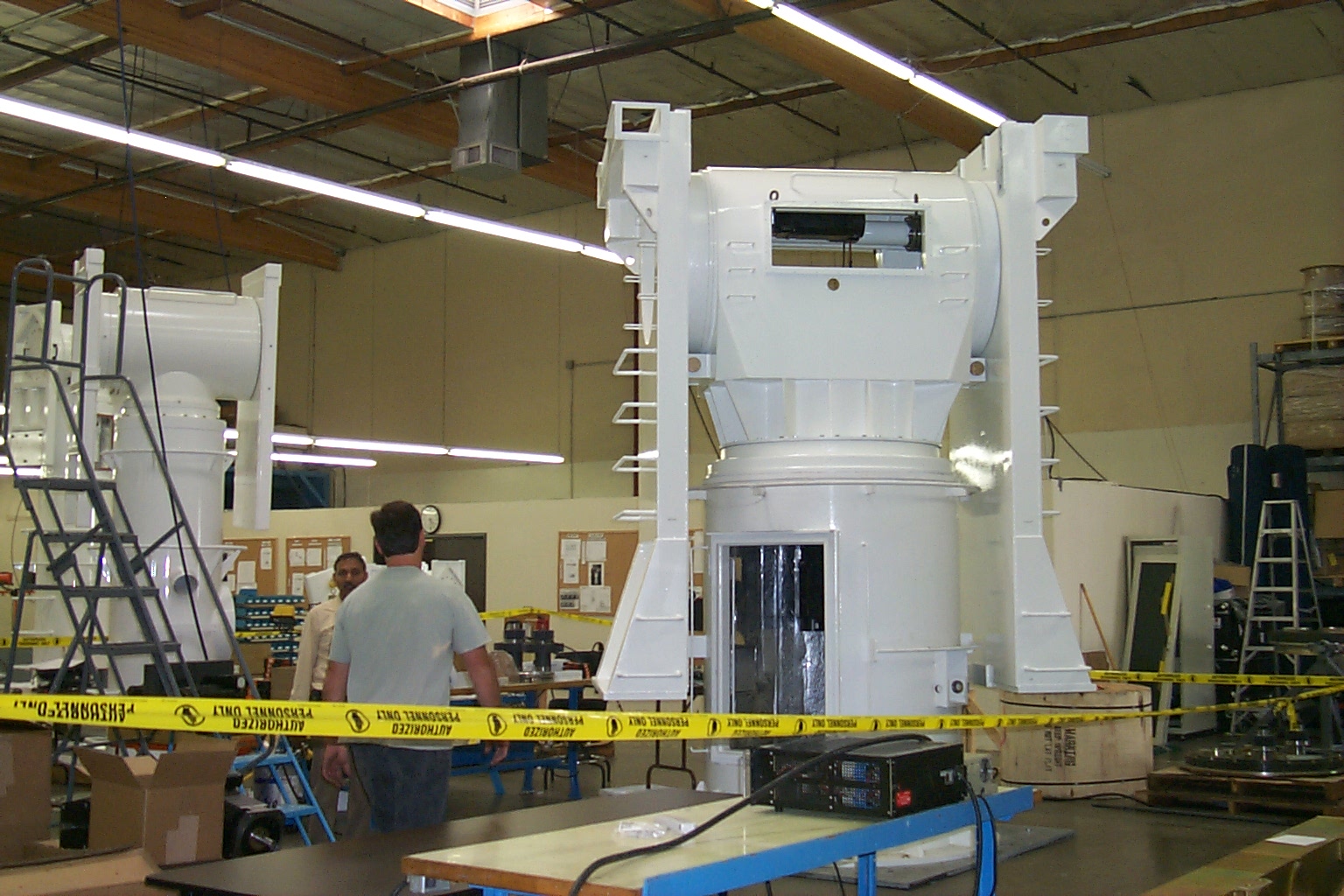
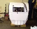
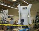
Assembled pedestal at EMP
Systems. Total weight of the pedestal without the reflector is about 29,200
pounds. The pedestal for the twin of the Berkeley antenna can be seen in the background (June 23, 1999). |
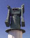 |
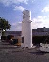
T-head and yoke arms (June 23, 1999). The total height of the pedestal is about 28
feet. |
|
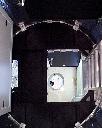 |
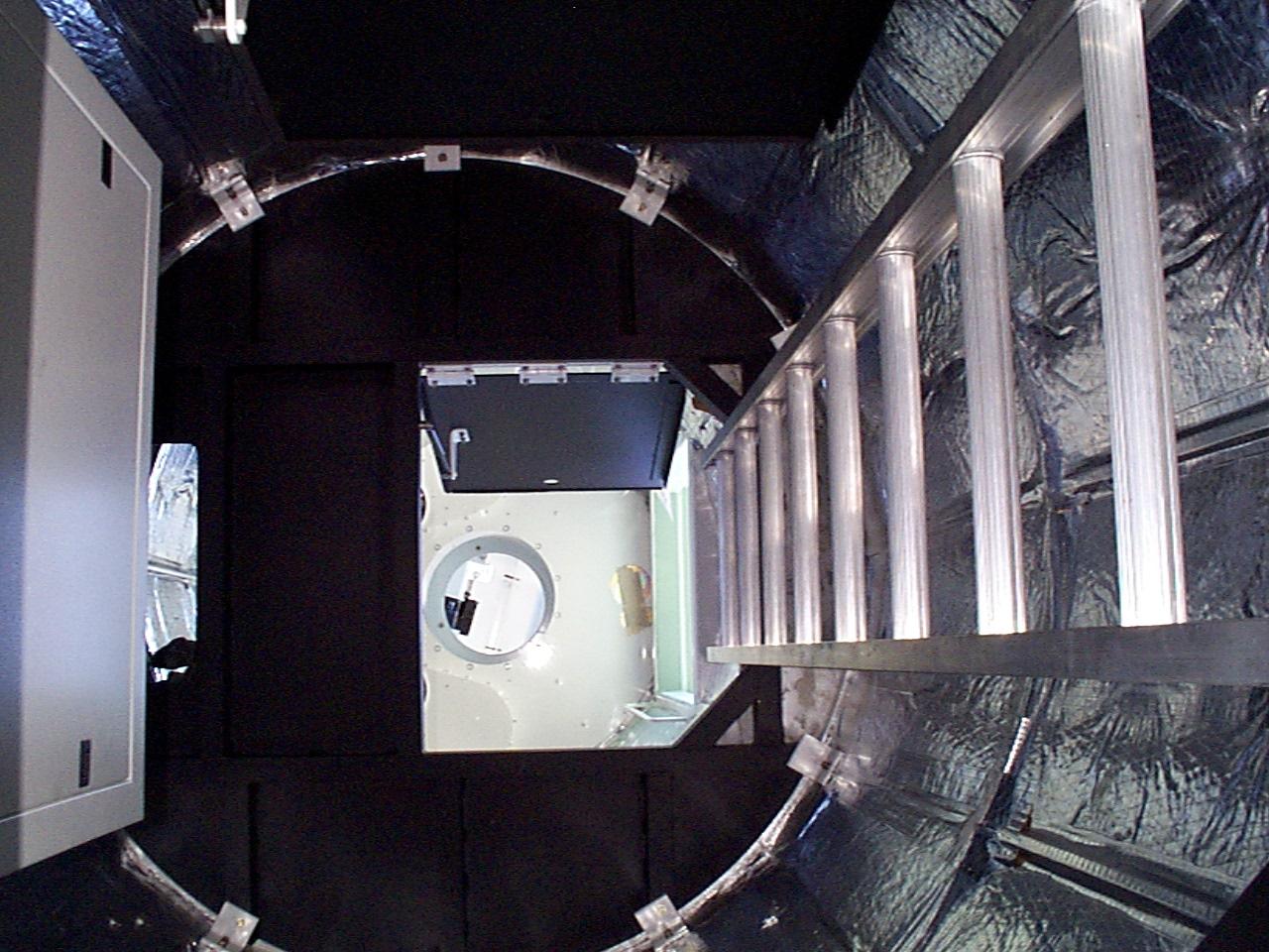
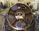
Interior view of the pedestal before installation of equipment cabinets and the cable
harness (June 23, 1999). |
 |
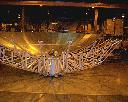
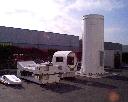
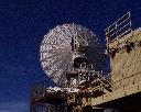
Fully assembled twin of the Berkeley antenna at EMP Systems (July 30,1999). |
|
 |
Fully assembled antenna system, consisting of riser base, T-head, gear boxes, yoke arms, counter weights,
and reflector at EMP Systems (July 30, 1999). |
|
|
|
|
| |
| |
| |
|