|
|

|
|
|
|
Visual Impact Analysis for the
Berkeley Ground Station
|
| |
| |
| Project Description |
| |
| In support of the HESSI
mission, NASA has provided funding for the installation of the Berkeley
Ground Station, which comprises a satellite tracking antenna, about 10
meters in diameter. This antenna is proposed to be deployed on the knoll
known as Goat Barn Rim Research Facility Reserve Site in the 1990
Long Range Development Plan and is located approximately 200 ft. downhill
from the Silver Lab and MSRI. The proposed dish pad would be about 44 ft.
on a side and the top of the dish would be about 40 ft. above ground. The
visibility of the dish from various campus and nearby local sites (Panoramic
Hill, LBNL, Botanical Garden), and regional sites (lower campus, downtown
Berkeley, etc.) has been investigated. A consultant, ArchView Media, has
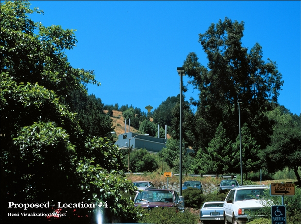
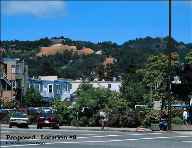
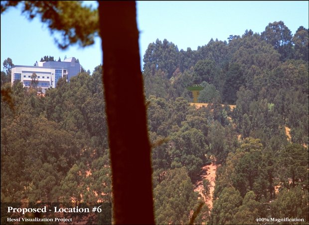
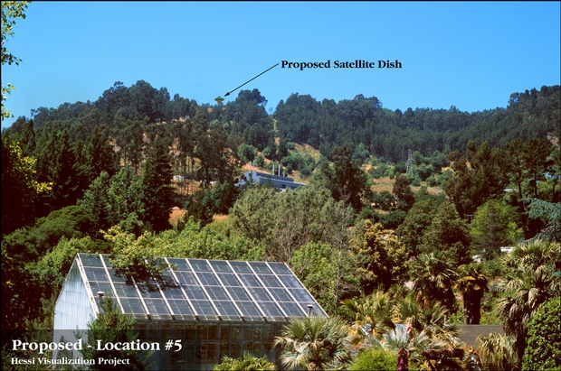
prepared a visual analysis to address this impact. Shown below are 9 visualizations
from different directions toward the proposed location of the Berkeley
Ground Station. |
| |
 |
View from Botanical Garden Parking Lot |
 |
View from Downtown Berkeley |
 |
View from Panoramic Hills Area |
 |
View from Panoramic Hills Area |
 |
View from South Side of Botanical Garden |
 |
View from LBNL |
| |
| Site Development |
| |
| Shown below are two polar
diagrams that illustrate passes of HESSI over the Berkeley area. These
diagrams represent the so-called station mask for the Berkeley Ground Station.
The outermost circle is the local horizon at zero degrees elevation, as
seen from the antenna site. North is up and West is to the left. The center
corresponds to the zenith at 90 degrees elevation, while the circles in
between are spaced 10 degrees in elevation. The brown areas are the horizon
obstruction contours, as seen from the antenna site, and the blue traces
are the typical trajectories that the HESSI spacecraft will follow across
the sky during a period of six days. HESSI will travel from west to east.
It is a mission requirement that data are to be transmitted from the spacecraft
to the ground station as soon as the elevation angle is 5 degrees. This
corresponds to a point half way between the outermost circle and the next
inner circle. The first of the two polar diagrams shows the present situation
with all trees in place. The project requires removal of a number of eucalyptus
trees of various size in the southwest, south, southeast and east since
these trees will cause absorption of the high-frequency transmissions from
the spacecraft to the ground station at low elevation angles. The second
polar diagram shows the station mask with these eucalyptus trees removed. |
| |
| |
|
|
Station
Mask - no trees removed |
| |
|
|
|
Station
mask with a number of trees removed
|
| |
| |
| Color Options |
| |
| The antenna pedestal and
the outside surface of the dish will be painted in colors that will blend
in well with the surroundings, in order to minimize the visual impact of
the facility on the environment. The inside surface of the dish needs to
be painted in white color to avoid overheating of the dish and the sensitive
receivers during daytime. The dish will be pointed up into the sky most
of the time in the stow position. A sample collection of available colors
is shown below. |

|

|

|
|
No. 24417
|
No. 34424
|
No. 34491
|
|
|
|
|

|

|

|
|
No.34533
|
No. 34554
|
No. 24670
|
|
|
|
|

|

|
|
|
No. 24516
|
No. 34672
|
|
| |
| |
| Schedule |
| |
| Construction at the site
needs to begin on September 1, 1998 and be will be by June 30, 1999 to
maintain the time schedule of the mission. Engineering, design and bidding
for the site work will commence in parallel with the environmental impact
studies. The preparation of the antenna site comprises removal of eucalyptus
trees, casting of the concrete foundation, paving of an area around the
antenna base, reinforcement of the access road, and installation of utilities,
drainage fencing and lighting. Delivery of the antenna system is expected
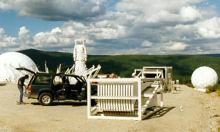
for July of 1999. The pedestal will be erected first. The parabolic reflector
dish will be assembled from individual segments and will then be mounted
on the pedestal. Installation of a similar antenna is shown in the photograph
below. |
| |
|
| |
|
Typical antenna construction scenario,
photographed in Alaska
|
|
| |
| |
| |
| |
|